Switched Network
circuit switched (e.g. telephone network)
Basic Network concepts
Direct link:
point-to-point
multiple access (e.g. ethernet, token ring)

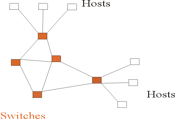
Switched Network
circuit switched (e.g. telephone network)
packet switched (e.g. Internet)
data is divided into packets
each packet is equipped with routing information
each packet is handled separately from the rest
packets are stored in switches/routers, forwarded towards destination

Routing:
Process of systematically determining how to forward packets to destinations in a switched network
Node (host, router/bridge/switch, terminal, printer)
Host a node that is a general-purpose computer
Switch/Router:
A device that stores and forwards packets based on
header information stored in each packet.
Routers interconnect networks of different types, switches do not.
Multiplexing:
Sending packets from multiple flows over the same physical link (wire)
Synchronous time-division multiplexing (dumm traffic lights)
Frequency division multiplexing (multilevel highways)
Statistical multiplexing
(uses a fair way of deciding which packet to send next, e.g. first-in-first-out, e.g. a four-way stop sign.)
The Challenge in network design
To bridge the gap between:
| what users expect | what technology can deliver |
| guarantee of delivery in-order delivery security from eavesdropping timely delivery |
bit errors in packets packets lost (dropped) physical links cut switches/routers and host crash |

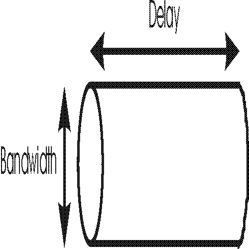
Pipe analogy:
| Water pipe | Network Link |
| Length | Delay |
| CrossSection | Bandwidth |
| Water in transit that pipe holds = Length * CrossSection |
Data in transit that link holds = Delay * Bandwidth |
Bit error rates on physical network links:
| Link type | One bit in error out of |
| Optical fiber | 10^12 = 1,000,000,000,000 |
| Copper | 10^7 = 10,000,000 |
| Wireless | 10^3 = 1,000 |
| Type | Bandwidth (in bits per second) |
| Voice (tel quality) | 48,000 bps |
| Modem (telephone) | 56,000 bps |
| Cable Modem & ADSL | 1,000,000 bps (1Mbps) |
| Local Area Network (standard) | 10,000,000 bps (10 Mbps) |
| Backbone network | 150,000,000 bps (150 Mbps) |
| State of the art fiber optics | 1,000,000,000 bps (1Gbps) |
| Dense Wavelength Division Multiplexing (DWDM) multiple light waves on a single optical fiber: Refs: 1 2 | 6,400,000,000,000 bps (6.4 Tbps) |
What is a protocol?
A precise set of rules defining how computers communicate.
Protocols come in layers
Director (strategy)
Manager (guides implementation)
Staff member (implements conceptually)
Support staff (supports the details of implementation)
Protocol layers in the Internet
Application (e.g. Netscape)
TCP (transport control protocol)
IP (internet protocol)
Physical layer (e.g. Ethernet)

Packet view:
|
Ethernet Header |
IP Header |
TCP Header |
Data |
Client application (e.g. Netscape)
Uses the http protocol (hypertext
transport protocol)
Allows user to specify which URL (uniform resource
locator) to access
Interprets html file (hypertext markup language)
Formats information for display
[Server application (e.g. Apache)]
Transport Layer (TCP)
Ensures packets are received in order
Ensures packets are not lost (by acknowledgement &
retransmission)
Internet Layer (IP)
Addressing scheme for nodes on the network
Data fragmentation and reassembly if required by the physical layer
Header format for packets
Example: HTTP (Hypertext transport protocol)
It is stateless: no memory of past requests
Uses TCP for data transfer
Uses MIME (multipurpose internet mail extensions) to encode data
Four steps:
1. client establishes TCP connection to port 80 of server.
(client = your laptop,
server = the computer holding the html files you wish to view
port = a "logical" input-output port for client-server communication via http)
2. client sends message requesting page at specified URL
GET /index.html HTTP/1.0 // relative URL, protocol version client can handle
Accept: text/html // kinds of data client can handle
Accept: text/plain
User agent: Lynx/2.4 libwww/2.1.4 // browser client uses
3. Server sends response to client
HTTP /1.0 OK 200 //response code, success
Server: NCSA / 1.4.2 // server software
MIME-version: 1.0
Content-type: text/html //type of document
Content-length: 107
<html> // the document itself
<head>
<title>
....
</html>
4. Client or server or both close the connection.
Separate connection required for each request (stateless)
Investigating HTTP with telnet:
%telnet www.cs.dal.ca 80 >& junk
GET /index.html HTTP/1.0
Accept: text/html
(Return)
(Return)
Error Detection
Add redundant information to a packet that can be used to determine if errors have been introduced during transmission.
Example: Add one more bit (0/1), the parity bit, to a sequence of N bits.
Even number of 1's among N bits => parity bit = 0
Odd number of 1's among N bits => parity bit = 1
Can detect single bit errors.
More sophisticated error detection methods are used on the Internet.
Error Correction
Objective: to reliably deliver packets over an unreliable link.
Ideas:
- Receiver applies error detection on each packet received
- If packet is error-free, an Acknowledgement is sent to the sender
- Sender retransmits packet if no Ack is received before timeout
Stop-and-wait algorithm
Sender sends packet and waits for Ack
If Ack does not arrive before timeout, sender retransmits
Drawbacks:
- duplicate packets possible. Use a sequence number for each packet.
- underutilizes the capacity of the network
Sliding window algorithm
Sender is allowed to send more than one packet before receiving an Ack
Local Area Networks
Ethernet
- A link, with multiple nodes plugged in
- Each node can tell when the link is idle
- Node transmits only when link is idle
- Node listens while it transmits, and can detect a collision
- If collision is detected, node waits a while and retransmits
- All nodes receive all packets
- A node only saves the packets addressed to it
Notes:
- Ethernet works well when not too loaded
Token ring
Another shared medium technology that works over longer distances
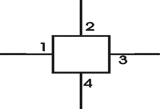
Switch: A device that has multiple input/output ports connected to links.
It receives incoming packets from links and transmits them onto other links
Links and ports are assumed bidirectional.
Packet header contains information to help switch forward the packet.

Three approaches to forwarding packets
1. Source Forwarding
2. Virtual Circuit or Connection-oriented (ATM)
3. Datagram or connectionless (Internet)
Source forwarding
Each packet has an ordered list of port numbers it should follow

Problems:
- Sender must know the map of the full network
- Packet header has no fixed length
- Hence not scalable!!!
Datagram or connectionless forwarding (Internet)
Each packet carries the destination (and source) address.
Each switch has a forwarding table,
showing the outgoing port y for each destination D.
D -> y
Notes:
- no setup or teardown phase
- no way of knowing whether a packet can be delivered
- Quality of service cannot be guaranteed
- Easy to route around a crashed switch or link
Virtual Circuit or Connection-oriented (ATM)
For a connection between two nodes,
a virtual circuit V is set up.
Each packet carries a virtual circuit identifier for V.
Each switch has a table showing
the outgoing port y for packets that arrive at port x and belong to virtual circuit V.
(V, x) -> y
In setup phase of virtual
circuit V,
table entries are created for V in all switches on V
by consulting the forwarding tables in the switches.
In teardown phase, table entries are removed.
Notes:
- Quality of Service guarantee possible by allocating resources to each virtual circuit V.
- a crashed switch or link requires new setup of the virtual circuits it services (disruption).
Routing
Objective: To construct the forwarding tables in each switch/router.
Common problem in virtual circuit & datagram approach
Any solution must deal with:
- node or link failures
- addition of new nodes or links
- time-varying loads on different links
Basic idea is flooding:
- each node knows how to reach its immediate neigbours
- the totality of this knowledge is disseminated to all nodes
- each node has knowledge of the full network and can compute shortest paths to all other nodes.
Difficulties:
- conditions are time-varying, hence flooding must be repeated often
- it is difficult to prevent obsolete information from circulation.
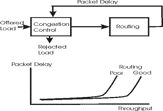
Congestion Control
Controls how much of the offered load to allow into the network.
Based on measured packet delay in operation.
As routing algorithm is successful in keeping delay low,
congestion control allows more traffic into the network.

Flow Control
In host-to-host communication, prevents the sender host from overrunning the receiver host with data.
Employs a variation of the sliding window algorithm.
Packet delay in a link

1. processing delay:
time between packet received at head node of a link and packet assigned to outgoing link queue. ("delay at
the reception").
Depends on CPU/memory speed and complexity of protocol.
2. queuing delay: time
between packet assigned to queue and packet transmitted. ("waiting in line").
Depends on traffic conditions.
3. transmission delay:
time between first and last bit of packet transmitted. ("squeezing through").
Depends on link capacity (in Mbps).
4. propagation delay:
time between last bit transmitted at head node and last bit received at tail node of a link ("physical transport").
Depends on the speed of light in the medium of the link (optical fiber, copper, air).
Hierarchical
- routing
- addressing
Routing and packet forwarding is at the IP layer (Internet Protocol)
IP packet header:
- Source address
- Destination address
- Header length
- Packet length (header+data)
- Number of hops till self-destruction
- Protocol above IP (e.g. TCP)
Addresses
- globally unique
- 32 bits long
- hierarchical: network part + host part
| class | network bits | number of networks in the world | host bits | number of hosts in network | total number of hosts in the world |
| A | 7 | 2^7 = 128 | 24 | 16,777,216 | 2 billion |
| B | 14 | 2^14 = 16,384 | 16 | 65,536 | 1 billion |
| C | 21 | 2^21 = 2,097,152 | 8 | 256 | 0.5 billion |
Classless routing:
- hand out a group of contiguous class C addresses sharing common prefix.
- treat group as a single network
Next Generation Internet Protocol (IP version 6)
Addresses are now 128 bits long
(enough to give an address to each square foot of the surface of the earth).
Transport Control Protocol (TCP)
- offers reliable, in-order delivery of packets over IP.
- congestion control
- flow control
- demultiplexing (multiple programs on same host communicate with peers)
TCP Header Format
- Source Port
- Destination Port
- Sequence number (of first byte in packet from sender to receiver)
- Acknowledgement (indicates Ack packet from receiver to sender)
- Advertised window (in Ack packet, informs sender on receiver ability)
- Header Length
TCP operation
Timeout value is determined from recently measured Round
Trip Time
between sender and receiver.
Triggered timeout is taken to imply network congestion.
Congestion control limits how much data the sender is allowed to have in transit at any given time.
References